
You're standing at the spigot, hose in one hand and a half-scribbled sketch of your yard in the other, wondering why every irrigation guide talks about GPM and PSI like you should already know yours. Take a deep breath — you're not alone. Whether you're pulling water from a city meter or a well, nailing down your sprinkler system's design capacity is the single most important thing you'll do before buying a single head or digging a single trench. Let's walk through it step by step, and by the end you'll have two numbers that make every other decision fall into place.
Step 1 — Determining Water Pressure (PSI)
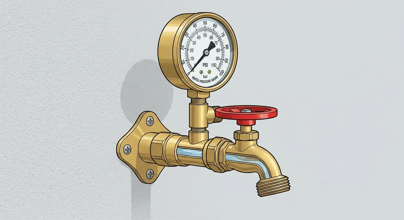
Attaching a Pressure Gauge
Start with static water pressure — the pressure in your pipes when nothing is moving. Grab a standard pressure gauge (under $15 at any hardware store) and thread it onto the outdoor faucet closest to your water meter. Attach a water pressure gauge to an outside faucet and record the static pressure in PSI 1. Before you turn the faucet on, walk through the house and make sure no other water is running — no dishwasher, no washing machine, no toilet refilling. Even a trickle will drag your reading down and throw off every calculation that follows.
Crack the faucet open fully and read the gauge. That number is your static water pressure in PSI. Write it down somewhere you won't lose it — you'll need it again when you calculate working pressure.
Typical residential static pressure ranges:
- Below 40 PSI — low pressure; may require a booster pump
- 40–80 PSI — normal residential range
- Above 80 PSI — high pressure; a pressure-reducing valve (PRV) is likely already installed, or should be
If you've got a system already running and one zone suddenly feels weak, don't jump straight to blaming the supply. One experienced plumber advised: "Turn all the heads off in that zone and look for a leak" 2. A cracked lateral line or a blown head gasket can bleed off enough pressure to make the whole zone limp, and it's a lot cheaper to fix than re-plumbing your main.
Step 2 — Determining Water Volume (GPM)
Your maximum available flow rate — gallons per minute — depends on either your water meter size or, if you're connected directly to the city main with no meter, your service line size. Either way, you're looking for the ceiling you shouldn't exceed.
Option A: Using Your Water Meter Size
The easiest route: read the meter size stamped right on the meter body. Look for "5/8", "3/4", or "1" cast into the housing. Match it to the table below for the maximum safe flow rate.
| Meter Size | Maximum Safe Flow Rate |
|---|---|
| 5/8" | 7.5 GPM |
| 3/4" | 11 GPM |
| 1" | 16.5 GPM |
| 1-1/2" | 30 GPM |
| 2" | 55 GPM |
These figures represent 75% of the meter's rated maximum — the industry-standard ceiling to avoid meter wear and pressure loss.
Option B: Measuring Your Service Line Size
No meter? You'll need to measure the service line itself. Since the pipe is buried and you can only access its outside surface, measure the circumference, not the diameter. Wrap a flexible tape or a piece of string around the pipe, mark where it meets, then measure that length. Compare it to the table below.
| Outside Circumference | Pipe Material | Nominal Pipe Size |
|---|---|---|
| 2-3/8" – 2-5/8" | Copper | 3/4" |
| 3-1/4" – 3-1/2" | Copper | 1" |
| 4-1/8" – 4-3/8" | Copper | 1-1/4" |
| 3-1/4" – 3-1/2" | Galvanized Steel / PVC | 3/4" |
| 4-1/8" – 4-3/8" | Galvanized Steel / PVC | 1" |
| 5-1/8" – 5-3/8" | Galvanized Steel / PVC | 1-1/4" |
If you're unsure of the pipe material, copper is a reddish-brown/orange color; galvanized steel is dull grey; PVC is white or cream-colored.
Once you've got the nominal pipe size, here's your maximum safe flow rate at typical residential pressures:
| Service Line Size | Maximum Safe Flow Rate |
|---|---|
| 3/4" | 11 GPM |
| 1" | 16.5 GPM |
| 1-1/4" | 25 GPM |
| 1-1/2" | 30 GPM |
| 2" | 55 GPM |
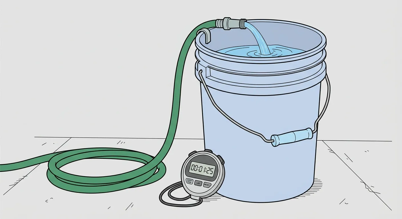
Tables are great for planning, but if you want a real-world check — or you're on a well and none of the meter tables apply — you can measure flow directly. Fill a 5-gallon bucket from an outside faucet, time the fill, then calculate GPM = (5 gallons / seconds) × 60 3. Run the faucet wide open and keep everything else in the house off while you time it. For an even quicker read, a flow meter measuring gauge attaches to your hose bib and gives a direct GPM reading 4. Either method grounds your numbers in what your pipes actually deliver, not just what the chart says they should.
Step 3 — Calculating Your System Design Capacity
Your System Design Capacity is the maximum GPM you should plan to use when laying out irrigation zones. Push past this number and you'll see pressure drops that starve the farthest heads, uneven coverage, and premature wear on your meter.
The formula is straightforward:
System Design Capacity = Available GPM × 0.75
Take the GPM value from your meter or service line table and multiply by 0.75. That 25% safety margin isn't arbitrary — it leaves room for a toilet flush, a running sink, or the washing machine kicking on while your sprinklers are running.
Example:
- Water meter size: 3/4" → Available GPM: 11
- System Design Capacity: 11 × 0.75 = 8.25 GPM
This means no single zone should run more than 8.25 GPM worth of sprinkler heads at once.
Manufacturers also publish charts that fold static pressure, meter size, and service line size together to give you a design capacity number directly. Hunter's System Design Capacity Chart uses static pressure, meter size, and service line size to determine maximum GPM 1. If you'd rather look up a value than do the math, those charts are a solid cross-check against your own calculation.
Step 4 — Determining Working Pressure
Your working pressure is the PSI you'll use when selecting sprinkler heads and calculating precipitation rates. It's always lower than your static pressure because water loses energy fighting its way through pipes, fittings, the backflow preventer, and valves. Working pressure is calculated by subtracting friction loss and elevation changes from static pressure at the point of connection 5.
Use this rule-of-thumb table based on your static pressure reading:
| Static Pressure (PSI) | Subtract | Estimated Working Pressure |
|---|---|---|
| 40–50 PSI | 5 PSI | 35–45 PSI |
| 51–75 PSI | 15 PSI | 36–60 PSI |
| 76–100 PSI | 20 PSI | 56–80 PSI |
| Above 100 PSI | 25 PSI | ~75+ PSI |
Example:
- Static pressure: 65 PSI
- Subtract 15 PSI for system losses
- Working pressure: 50 PSI
Match your sprinkler heads to this working pressure. Run a 30-PSI head at 50 PSI and it'll mist, wasting water to wind and evaporation. Run a 45-PSI head at 25 PSI and the throw radius collapses, leaving dry rings between heads. Get this number right and your coverage map actually means something.
Putting It All Together
After working through the four steps, you should have two concrete numbers:
- System Design Capacity (GPM) — the maximum flow rate across any single irrigation zone
- Working Pressure (PSI) — the operating pressure to use when selecting and spacing heads
Design capacity is the maximum safe flow available for the sprinkler system, determining how many heads can operate simultaneously 6. For example, if your design capacity comes out to 18 GPM, you can run six heads that each draw 3 GPM on one zone — but not seven. It's the hard cap that keeps your system from outrunning its water supply.
Example summary:
- Static pressure: 65 PSI → Working pressure: 50 PSI
- Meter size: 3/4" → Available GPM: 11 → Design Capacity: 8.25 GPM
With these numbers in hand, you can look up the precipitation rate and throw radius for any sprinkler head at 50 PSI, then add heads to each zone until you approach — but don't exceed — 8.25 GPM. This process ensures every zone delivers consistent coverage, avoids pressure drop failures, and stays within what your water supply can safely provide.
A couple of final guardrails to keep in mind as you design. Keep water velocity below 5 feet per second to prevent water hammer and pipe damage 7. If you've got an existing system and hear pipes banging when a zone shuts off, one experienced plumber recommended: "Enable the Well Recovery feature on your controller to add a delay between station runs" 8. That brief pause lets pressure dissipate before the next valve opens, sparing your pipes the shock.
These two values — design capacity and working pressure — carry through every remaining design decision: zone count, head selection, pipe sizing, and controller programming. Get them right now and you'll spend a lot less time troubleshooting later.